成为控制大师[1]——闭环控制与滤波器设计

介绍

在写了这么多视觉和深度学习的博客之后,我也总算念完了大二了,接下来就要逐步成为控制大师。

在很早之前我尝试过做无人机,但是不知道为什么无人机飞起来特别困难,在之后我尝试了穿越机以及穿越机的PID调参,我忽然明白了些什么但是不多,所以本期博客就要详细地叙述一下。为了有一个良好的参考,这里我选择了一个编码电机用于演示。

开环控制很简单,我们给多少PWM它就出多大力,至于负载变没变、电池电压掉没掉,它一概不管,转速飘了也没人发现。闭环就不一样了:我们实时把电机的实际转速测出来,和期望速度比较,差了就补、多了就减,这样负载再怎么变,转速也能稳在目标附近。要闭环,先得有一路靠得住的反馈,所以才用编码电机来当例子——它尾巴上带着编码器,转了多少自己会报出来。
1

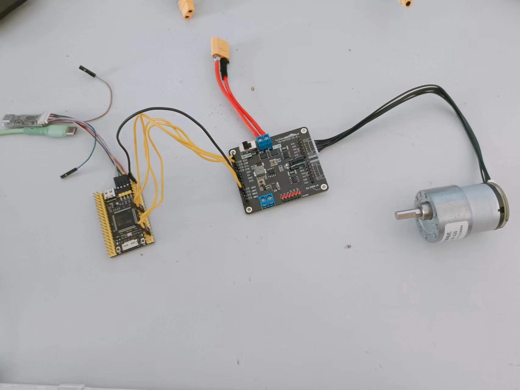
单片机选择的是f407vet6,控制板是亚博的,编码电机是同学的(硬抢),然后我们需要完成一下最基本的stm32配置。

设备驱动

编码电机的驱动分两步:

  • 让一个定时器输出PWM波,负责驱动电机转动
  • 把另一个定时器配成编码器接口,负责读取电机转了多少

PWM的道理其实不复杂。定时器内部就是个不断累加的计数器,时钟每来一拍加一,加到自动重装载值(ARR)就归零重来;同时硬件拿计数值和比较寄存器(CCR)比大小,比CCR小就输出高电平,比CCR大就输出低电平,于是一个周期里高电平占的比例就由CCR决定,这就是占空比。频率和占空比的计算就是:

要调速就改CCR,要改PWM频率就动PSC和ARR。

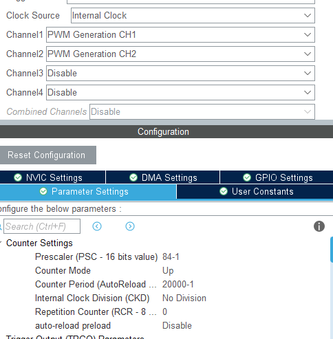
PWM输出定时器,这里我用了TIM1,TIM1在APB2总线上,频率为84MHz,经过分频和自动重装载后可以输出50Hz的PWM波
2

照图中的参数算一遍:84MHz的时钟先过84分频,再用20000个计数当一个周期,84MHz除以84再除以20000,正好是50Hz。图中CH1和CH2都开成了PWM输出,我们这套代码只用到了CH1。

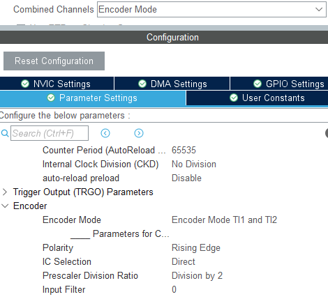
编码器部分使用了TIM2,我们只需要它数数,所以预分频不动,计数周期(AutoReload)保持默认的65535,把16位计数器用满。编码器模式开TI1 and TI2,两路信号都参与计数,下面的Prescaler Division Ratio选的是Division by 2,也就是每两个边沿才记一个数。
3

编码器出来的是电机尾部两路相差90度的方波,一路叫A相一路叫B相。正转的时候A相超前B相,反转的时候B相超前A相,定时器盯着这两路的跳变顺序,就能自动让CNT加一或者减一,计数值里天然带着方向信息;而且这个过程纯硬件完成,不需要CPU插手,我们隔一段时间去读一次CNT就行。Division by 2把计数率降了一半,分辨率相应粗一点,好处是高速时计数值不至于涨得太快,想要更细的分辨率把它改回No Division即可。

然后我们还需要一个串口用于绘制波形,这里选择的是VOFA+上位机(好看,比匿名上位机好看),串口配置过于基础,这里不说了。

测速

大家可能会好奇,为什么我不使用一个TIM中断进行定时测速?那我们就不得不说一下中断是什么了。

中断是时序恶魔:

我这么说可能击碎了很多人脆弱的心脏,但事实上对于单核CPU或者说单片机而言,中断是噩梦一般的存在。

我们都知道程序保存在连续的内存空间内,CPU加载指令到缓存中可以非常方便地执行。如果产生了一个IRQ,打断了当前正在运行的指令,CPU就不得不跳转到另一段连续的内存空间中去,本来安排好的节奏全乱套了。中断的响应要花时间,进出中断还要保存、恢复现场,开销一点不小;如果主进程是一个对时间要求非常高的进程,这些都会影响到它的执行时机。为什么我们在控制的时候一定要做好对时间的把握?因为外部的干扰需要实时反馈,中断会破坏这个实时性,让控制机错过很多信息。举个例子:

小明驾车出去玩,当车辆行驶在公路(主进程)时忽然来了一个电话(中断),这时会产生两个情况:

  • 小明接电话了,但是在接电话时迎面驶来了一个失控的货车,小明观察不及时而寄了
  • 小明没接电话,而是选择在休息站(主进程空闲)接电话,这时迎面驶来一个失控的货车,小明及时反应而活了下来

没错,这个故事告诉我们一心不可二用,单片机也是如此(当然多核中断随便用,因为可以把任务分散给不同核心,但是单核就不可以了)。

单片机控制电机的时候需要实时查看电机情况,不管响应是超前还是滞后,都得先把电机的状态拿到手,等超过了调整时间再反应过来就晚了,控制会直接失控。

那不用中断,测速的问题怎么解决?其实编码器接口本来就在后台硬件计数,我们只要在主循环里按固定节拍去读CNT,把两次的差值算出来,速度就出来了。这种固定时间数脉冲的方法叫M法,适合中高速场合;对应的还有T法,测的是两个脉冲之间的时间,低速时更准。我们这个编码器转起来脉冲密密麻麻的,直接用M法就够。

如此说来我们就应该实现主程序计时。

1
2
3
4
5
6
7
8
9
10
11
12
13
14
15
16
17
18
19
20
21
#define TimePeriod 100

uint16_t U_ABS(uint16_t a,uint16_t b){
return a > b ? a - b : b - a;
}

uint32_t last_system_time = 0;


void Motor_update(TIM_HandleTypeDef *encoder_tim, Motor_t *motor) {
// HAL_GetTick()可以获取到1ms自增一次的定时
if(HAL_GetTick() - last_system_time >= TimePeriod){
motor->encoder = encoder_tim->Instance->CNT;
// 编码器异常情况需忽略
if(U_ABS(motor->encoder,motor->last_encoder) <= 10000) {
motor->speed = U_ABS(motor->encoder, motor->last_encoder);
last_system_time = HAL_GetTick();
}
motor->last_encoder = encoder_tim->Instance->CNT;
}
}

这样,电机参数更新的函数就实现了。HAL_GetTick()是SysTick撑起来的1ms计数,所以时间片的精度就是1ms,想换周期只要改TimePeriod这一个宏。这套写法放到实时操作系统里也一样能用,让任务按固定周期跑。

1
2
3
4
5
6
7
8
9
10
11
12
13
14
15
16
17
18
19
20
21
22
typedef struct Motor Motor_t;

struct Motor{
uint16_t encoder;
uint16_t last_encoder;

// 减速比, 用于确定轴位置
uint16_t output_ratio; // 输出比例
uint16_t input_ratio; // 输入比例

float angle;
uint16_t speed;
};

#define Motor_INIT(output_ratio_i, input_ratio_i) { \
.encoder = 0, \
.last_encoder = 0, \
.output_ratio = output_ratio_i, \
.input_ratio = input_ratio_i, \
.angle = 0, \
.speed = 0 \
};

那么可能会有人问,100ms一次的定时会不会不准确呢?答案很简单,编码器计数值在10000以内我们就认为没有溢出,假设每个计数对应0.5cm的位移,那10000个计数就对应50米,要让计数在一个周期内溢出,电机的速度得远超声速。所以这种速度完全足够了。(你在小看单片机的速度)

顺便说下这个10000是怎么来的。TIM2的计数器是16位的,从0数到65535再绕回0,如果中间真的绕了一圈,两次读数的差值就成了乱码。正常情况下100ms里电机最多走几百个计数,离10000还差得远,所以超过10000就当成异常丢掉,免得把速度环带跑偏;偶尔的采样抖动或者编码器干扰都可能让某一拍差值离谱。如果想严格一点,可以按int16_t去解释差值,让计数器绕圈也能自动接上,我们这个场景用不上,先图省事。

另外注意,这里算出来的速度单位是“每个TimePeriod里编码器走了多少个计数”,不是物理转速。想换成转/分,得先知道输出轴转一圈对应多少个计数——这个值跟编码器线数、分频设置和减速比都有关系,懒得算就用手慢慢转一圈输出轴,看CNT总共变了多少,实测一下最省事。拿到这个数以后,转速就等于计数除以它,再除以周期秒数、乘以60。

然后在主程序实时输出速度即可。
4

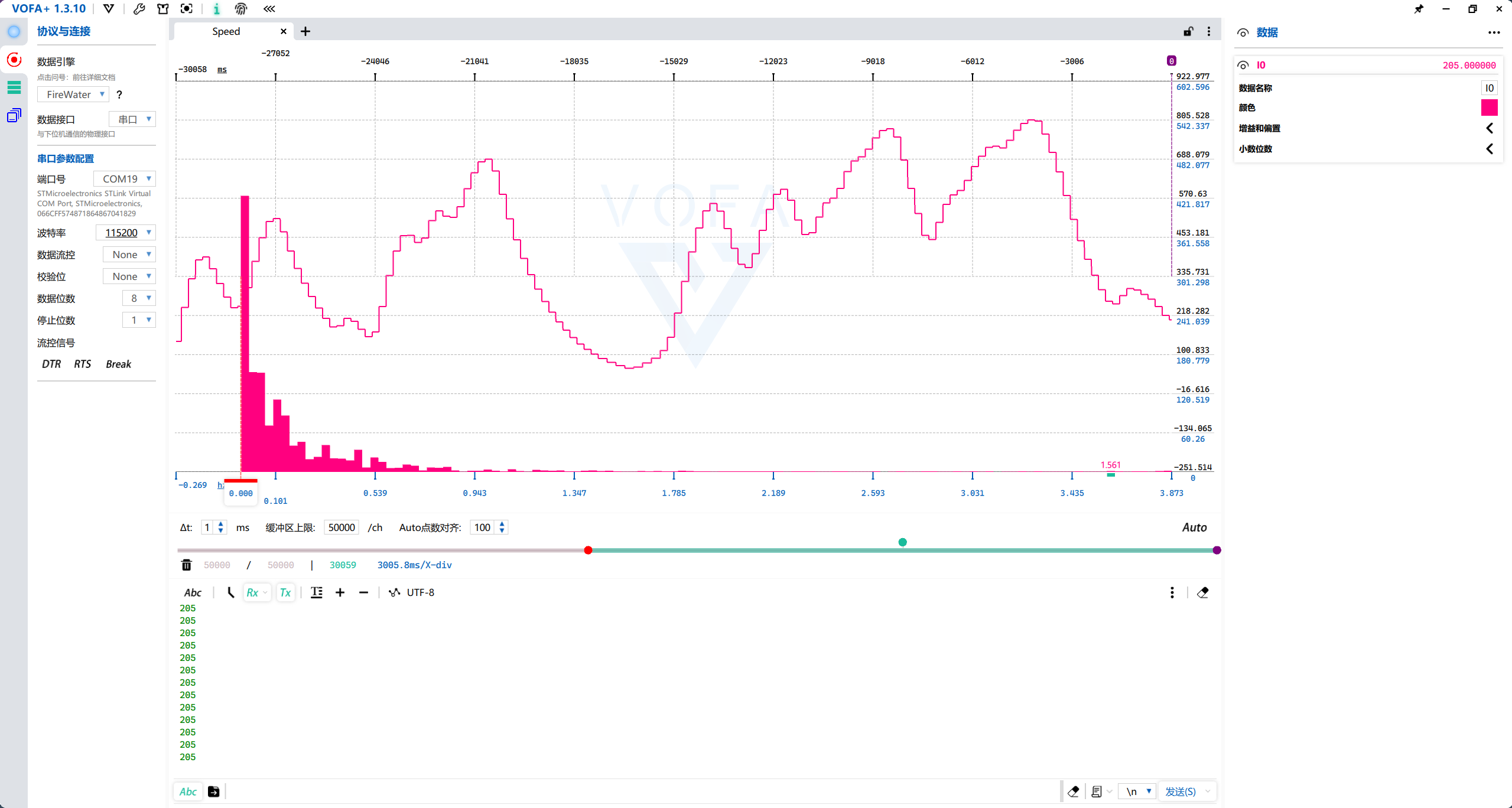
这张是滤波前的原始速度,曲线呈现明显的台阶状,这来自编码器计数只有整数;毛刺和抖动也很明显,拿这种数据直接丢给PID的话,微分项会被噪声放大,输出跟着乱抖。光靠这些数据去控制肯定不行,需要通过频谱分析找出噪声分布,再进行低通滤波,确保获取一个准确的速度。

数字信号处理(DSP)

既然噪声混在高频里,那就用低通滤波器把高频压下去,不过在选参数之前,得先搞清楚有效信号在哪个频率上。我们把串口数据保存下来,然后利用matlab绘制一下FFT,确定一下频率中心、带宽以及采样率。

顺便说下采样率这件事。我们每100ms更新一次速度,相当于对速度信号以10Hz的频率采样。采样定理要求采样率至少是信号最高频率的两倍,否则高频成分会折叠到低频里去,混在一起再也分不开,所以10Hz采样能分辨的最高频率是5Hz,也就是奈奎斯特频率。滤波器的截止频率要放在有效信号和噪声之间,又不能超过这个上限。

1
2
3
4
5
6
7
8
9
10
11
12
13
14
15
16
17
18
19
20
21
% 自己改数据位置
fl = fopen("C://Users/28211/Desktop/Serial.txt", "r");
% 文件的每一行都是速度值
Y = textscan(fl, '%d');
Y = Y{1};
fclose(fl);

% 绘制fft波形
FFT_Y = fft(Y);

FFT_Y_shifted = fftshift(FFT_Y);

% 计算频率轴
N = length(FFT_Y);
n = 0:N-1;
f = (n - N/2) * 10 / N; % Fs是采样频率

plot(f, abs(FFT_Y_shifted));
xlabel('Frequency (Hz)');
ylabel('Amplitude');
title('FFT of Signal');

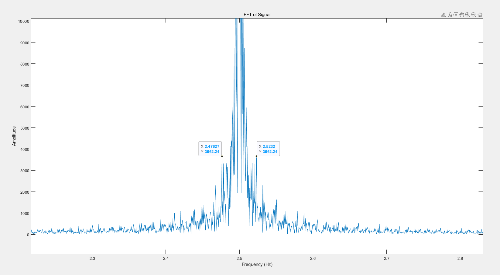
绘制一下图像可以得到:

5

matlab的代码没什么好说的,把每行一个的速度值读进来,做FFT,用fftshift把零频挪到中间,再按f = (n - N/2) * 10 / N算频率轴,其中10就是采样率,N是数据点数,横轴因此覆盖-5Hz到5Hz,每根谱线的间隔是fs/N。这个10是写死的,以后换了采样率记得一起改,不然频率轴就对不上了。

从图上看,2.5Hz左右数据分布密度最大,其他的集中在2.47627Hz到2.5232Hz之间,我们就可以确定中心频率为2.5Hz,频率宽度在0.04693Hz。采样率就是我们更新电机速度的频率,我这里的TimePeriod是100,也就是100ms,换算频率为10Hz,所以我们就用10Hz的采样率进行计算。

这个结果说明速度的波动集中在2.5Hz附近,再往上的成分基本就是噪声了。低通滤波器的特征频率就先取在2.5Hz旁边,滤波的力度再通过Q去调,Q大了滤得松,Q小了滤得狠。

接下来我们实现滤波器的设计。这里用的是双二阶(biquad)IIR滤波器,一个二阶节就够实现低通、高通、带通这些常见类型,系数用的就是经典的RBJ公式,网上那些“双二阶滤波器计算器”算的都是这一套。它的传递函数长这样:

代码里a、b各存三个系数,w存两个内部状态,计算结构是转置直接II型,代码短、占的存储也少。先看头文件里的定义:

1
2
3
4
5
6
7
8
9
10
11
12
13
14
15
16
17
18
19
20
21
22
23
24
25
26
27
28
29
30
31
32
33
#define PI 3.14159265358979323846

typedef enum {
DSP_IIR_FILTER = 0,
DSP_FIR_FILTER = 1,
DSP_LPF_FILTER = 2,
DSP_HPF_FILTER = 3,
DSP_BPF_FILTER = 4,
DSP_BSF_FILTER = 5,
DSP_NOTCH_FILTER = 6,
DSP_PEAKING_FILTER = 7,
DSP_ALLPASS_FILTER = 8,
DSP_DC_REMOVAL_FILTER = 9,
DSP_COUNT = 10
} DSP_FilterType;

typedef struct {
double a[3];
double b[3];
double w[3];
} DSP_Filter_t;

/*** 滤波器初始化
* @param filter 滤波器
* @param type 滤波器类型
* @param f0 截止频率
* @param fs 采样频率
* @param Q 品质因数
* @param gain 增益
* */
void DSP_Filter_Init(DSP_Filter_t *filter, DSP_FilterType type, double f0, double fs, double Q, double gain);

double DSP_Filter_Process(DSP_Filter_t *filter, DSP_FilterType type, double x);

初始化函数的几个参数各有各的用处:f0是特征频率,对低通来说就是拐点;fs是采样率,本次取10Hz;Q是品质因数,管的是过渡带的陡缓,巴特沃斯响应取0.7071,Q越大通带边缘越容易翘起来,Q小于0.5就没有峰值了,曲线从低频一路缓缓压下去;gain是留给增益的,目前几个初始化函数里都没用到。

然后我们看看C语言如何实现具体功能:

1
2
3
4
5
6
7
8
9
10
11
12
13
14
15
16
17
18
19
20
21
22
23
24
25
26
27
28
29
30
31
32
33
34
35
36
37
38
39
40
41
42
43
44
45
46
47
48
49
50
51
52
53
54
55
56
57
58
59
60
61
62
63
64
65
66
67
68
69
70
71
72
73
74
75
76
77
78
79
80
81
82
83
84
85
86
87
88
89
90
91
92
93
94
95
96
97
98
99
100
101
102
103
104
105
106
107
108
109
110
111
112
113
114
115
116
117
118
119
120
121
122
123
124
125
126
127
128
129
130
131
132
133
134
135
136
137
138
139
140
141
142
143
144
145
146
147
148
149
150
151
152
153
154
155
156
157
158
159
160
161
162
163
164
165
166
167
168
169
170
171
172
173
174
175
176
177
178
179
180
181
182
183
184
185
186
187
188
189
190
191
192
193
194
195
196
197
198
199
200
201
202
203
204
205
206
207
208
209
210
211
212
213
214
215
216
217
218
219
220
221
222
223
224
225
226
227
228
229
230
231
232
233
234
235
236
237
238
239
240
241
242
243
244
245
246
247
248
249
250
251
252
253
254
255
256
257
258
259
260
261
262
263
264
265
266
267
268
269
270
271
272
273
274
275
276
277
278
279
280
281
282
283
284
285
286
287
#include <math.h>
#include "DSP.h"

// IIR
void DSP_IIR_Filter_Init(DSP_Filter_t *filter, double f0, double fs, double Q, double gain) {
double w0 = 2 * PI * f0 / fs;
double alpha = sin(w0) / (2 * Q);
double a0 = 1 + alpha;
filter->a[0] = 1 / a0;
filter->a[1] = -2 * cos(w0) / a0;
filter->a[2] = (1 - alpha) / a0;
filter->b[0] = (1 - cos(w0)) / a0;
filter->b[1] = 2 * (1 - cos(w0)) / a0;
filter->b[2] = (1 - cos(w0)) / a0;
filter->w[0] = 0;
filter->w[1] = 0;
}

double DSP_IIR_Filter_Process(DSP_Filter_t *filter, double x) {
double y = filter->b[0] * x + filter->w[0];
filter->w[0] = filter->b[1] * x - filter->a[1] * y + filter->w[1];
filter->w[1] = filter->b[2] * x - filter->a[2] * y;
return y;
}

// FIR
void DSP_FIR_Filter_Init(DSP_Filter_t *filter, double f0, double fs, double Q, double gain) {
double w0 = 2 * PI * f0 / fs;
double alpha = sin(w0) / (2 * Q);
double a0 = 1 + alpha;
filter->a[0] = 1 / a0;
filter->a[1] = -2 * cos(w0) / a0;
filter->a[2] = (1 - alpha) / a0;
filter->b[0] = (1 - cos(w0)) / a0;
filter->b[1] = 2 * (1 - cos(w0)) / a0;
filter->b[2] = (1 - cos(w0)) / a0;
filter->w[0] = 0;
filter->w[1] = 0;
}

double DSP_FIR_Filter_Process(DSP_Filter_t *filter, double x) {
double y = filter->b[0] * x + filter->w[0];
filter->w[0] = filter->b[1] * x - filter->a[1] * y + filter->w[1];
filter->w[1] = filter->b[2] * x - filter->a[2] * y;
return y;
}

// LPF
void DSP_LPF_Filter_Init(DSP_Filter_t *filter, double f0, double fs, double Q, double gain) {
double w0 = 2 * PI * f0 / fs;
double alpha = sin(w0) / (2 * Q);
double a0 = 1 + alpha;
filter->a[0] = 1 / a0;
filter->a[1] = -2 * cos(w0) / a0;
filter->a[2] = (1 - alpha) / a0;
filter->b[0] = (1 - cos(w0)) / a0;
filter->b[1] = 2 * (1 - cos(w0)) / a0;
filter->b[2] = (1 - cos(w0)) / a0;
filter->w[0] = 0;
filter->w[1] = 0;
}

double DSP_LPF_Filter_Process(DSP_Filter_t *filter, double x) {
double y = filter->b[0] * x + filter->w[0];
filter->w[0] = filter->b[1] * x - filter->a[1] * y + filter->w[1];
filter->w[1] = filter->b[2] * x - filter->a[2] * y;
return y;
}

// HPF
void DSP_HPF_Filter_Init(DSP_Filter_t *filter, double f0, double fs, double Q, double gain) {
double w0 = 2 * PI * f0 / fs;
double alpha = sin(w0) / (2 * Q);
double a0 = 1 + alpha;
filter->a[0] = 1 / a0;
filter->a[1] = -2 * cos(w0) / a0;
filter->a[2] = (1 - alpha) / a0;
filter->b[0] = (1 - cos(w0)) / a0;
filter->b[1] = 2 * (1 - cos(w0)) / a0;
filter->b[2] = (1 - cos(w0)) / a0;
filter->w[0] = 0;
filter->w[1] = 0;
}

double DSP_HPF_Filter_Process(DSP_Filter_t *filter, double x) {
double y = filter->b[0] * x + filter->w[0];
filter->w[0] = filter->b[1] * x - filter->a[1] * y + filter->w[1];
filter->w[1] = filter->b[2] * x - filter->a[2] * y;
return y;
}

// BPF
void DSP_BPF_Filter_Init(DSP_Filter_t *filter, double f0, double fs, double Q, double gain) {
double w0 = 2 * PI * f0 / fs;
double alpha = sin(w0) / (2 * Q);
double a0 = 1 + alpha;
filter->a[0] = 1 / a0;
filter->a[1] = -2 * cos(w0) / a0;
filter->a[2] = (1 - alpha) / a0;
filter->b[0] = (1 - cos(w0)) / a0;
filter->b[1] = 2 * (1 - cos(w0)) / a0;
filter->b[2] = (1 - cos(w0)) / a0;
filter->w[0] = 0;
filter->w[1] = 0;
}

double DSP_BPF_Filter_Process(DSP_Filter_t *filter, double x) {
double y = filter->b[0] * x + filter->w[0];
filter->w[0] = filter->b[1] * x - filter->a[1] * y + filter->w[1];
filter->w[1] = filter->b[2] * x - filter->a[2] * y;
return y;
}

// BSF
void DSP_BSF_Filter_Init(DSP_Filter_t *filter, double f0, double fs, double Q, double gain) {
double w0 = 2 * PI * f0 / fs;
double alpha = sin(w0) / (2 * Q);
double a0 = 1 + alpha;
filter->a[0] = 1 / a0;
filter->a[1] = -2 * cos(w0) / a0;
filter->a[2] = (1 - alpha) / a0;
filter->b[0] = (1 - cos(w0)) / a0;
filter->b[1] = 2 * (1 - cos(w0)) / a0;
filter->b[2] = (1 - cos(w0)) / a0;
filter->w[0] = 0;
filter->w[1] = 0;
}

double DSP_BSF_Filter_Process(DSP_Filter_t *filter, double x) {
double y = filter->b[0] * x + filter->w[0];
filter->w[0] = filter->b[1] * x - filter->a[1] * y + filter->w[1];
filter->w[1] = filter->b[2] * x - filter->a[2] * y;
return y;
}

// NOTCH
void DSP_NOTCH_Filter_Init(DSP_Filter_t *filter, double f0, double fs, double Q, double gain) {
double w0 = 2 * PI * f0 / fs;
double alpha = sin(w0) / (2 * Q);
double a0 = 1 + alpha;
filter->a[0] = 1 / a0;
filter->a[1] = -2 * cos(w0) / a0;
filter->a[2] = (1 - alpha) / a0;
filter->b[0] = (1 - cos(w0)) / a0;
filter->b[1] = 2 * (1 - cos(w0)) / a0;
filter->b[2] = (1 - cos(w0)) / a0;
filter->w[0] = 0;
filter->w[1] = 0;
}

double DSP_NOTCH_Filter_Process(DSP_Filter_t *filter, double x) {
double y = filter->b[0] * x + filter->w[0];
filter->w[0] = filter->b[1] * x - filter->a[1] * y + filter->w[1];
filter->w[1] = filter->b[2] * x - filter->a[2] * y;
return y;
}

// PEAKING
void DSP_PEAKING_Filter_Init(DSP_Filter_t *filter, double f0, double fs, double Q, double gain) {
double w0 = 2 * PI * f0 / fs;
double alpha = sin(w0) / (2 * Q);
double a0 = 1 + alpha;
filter->a[0] = 1 / a0;
filter->a[1] = -2 * cos(w0) / a0;
filter->a[2] = (1 - alpha) / a0;
filter->b[0] = (1 - cos(w0)) / a0;
filter->b[1] = 2 * (1 - cos(w0)) / a0;
filter->b[2] = (1 - cos(w0)) / a0;
filter->w[0] = 0;
filter->w[1] = 0;
}

double DSP_PEAKING_Filter_Process(DSP_Filter_t *filter, double x) {
double y = filter->b[0] * x + filter->w[0];
filter->w[0] = filter->b[1] * x - filter->a[1] * y + filter->w[1];
filter->w[1] = filter->b[2] * x - filter->a[2] * y;
return y;
}

// ALLPASS
void DSP_ALLPASS_Filter_Init(DSP_Filter_t *filter, double f0, double fs, double Q, double gain) {
double w0 = 2 * PI * f0 / fs;
double alpha = sin(w0) / (2 * Q);
double a0 = 1 + alpha;
filter->a[0] = 1 / a0;
filter->a[1] = -2 * cos(w0) / a0;
filter->a[2] = (1 - alpha) / a0;
filter->b[0] = (1 - cos(w0)) / a0;
filter->b[1] = 2 * (1 - cos(w0)) / a0;
filter->b[2] = (1 - cos(w0)) / a0;
filter->w[0] = 0;
filter->w[1] = 0;
}

double DSP_ALLPASS_Filter_Process(DSP_Filter_t *filter, double x) {
double y = filter->b[0] * x + filter->w[0];
filter->w[0] = filter->b[1] * x - filter->a[1] * y + filter->w[1];
filter->w[1] = filter->b[2] * x - filter->a[2] * y;
return y;
}

// DC_REMOVAL
void DSP_DC_REMOVAL_Filter_Init(DSP_Filter_t *filter, double f0, double fs, double Q, double gain) {
double w0 = 2 * PI * f0 / fs;
double alpha = sin(w0) / (2 * Q);
double a0 = 1 + alpha;
filter->a[0] = 1 / a0;
filter->a[1] = -2 * cos(w0) / a0;
filter->a[2] = (1 - alpha) / a0;
filter->b[0] = (1 - cos(w0)) / a0;
filter->b[1] = 2 * (1 - cos(w0)) / a0;
filter->b[2] = (1 - cos(w0)) / a0;
filter->w[0] = 0;
filter->w[1] = 0;
}

double DSP_DC_REMOVAL_Filter_Process(DSP_Filter_t *filter, double x) {
double y = filter->b[0] * x + filter->w[0];
filter->w[0] = filter->b[1] * x - filter->a[1] * y + filter->w[1];
filter->w[1] = filter->b[2] * x - filter->a[2] * y;
return y;
}

void DSP_Filter_Init(DSP_Filter_t *filter, DSP_FilterType type, double f0, double fs, double Q, double gain){
switch(type) {
case DSP_IIR_FILTER:
DSP_IIR_Filter_Init(filter, f0, fs, Q, gain);
break;
case DSP_FIR_FILTER:
DSP_FIR_Filter_Init(filter, f0, fs, Q, gain);
break;
case DSP_LPF_FILTER:
DSP_LPF_Filter_Init(filter, f0, fs, Q, gain);
break;
case DSP_HPF_FILTER:
DSP_HPF_Filter_Init(filter, f0, fs, Q, gain);
break;
case DSP_BPF_FILTER:
DSP_BPF_Filter_Init(filter, f0, fs, Q, gain);
break;
case DSP_BSF_FILTER:
DSP_BSF_Filter_Init(filter, f0, fs, Q, gain);
break;
case DSP_NOTCH_FILTER:
DSP_NOTCH_Filter_Init(filter, f0, fs, Q, gain);
break;
case DSP_PEAKING_FILTER:
DSP_PEAKING_Filter_Init(filter, f0, fs, Q, gain);
break;
case DSP_ALLPASS_FILTER:
DSP_ALLPASS_Filter_Init(filter, f0, fs, Q, gain);
break;
case DSP_DC_REMOVAL_FILTER:
DSP_DC_REMOVAL_Filter_Init(filter, f0, fs, Q, gain);
break;
default:
break;
}
}


double DSP_Filter_Process(DSP_Filter_t *filter, DSP_FilterType type, double x){
switch(type) {
case DSP_IIR_FILTER:
return DSP_IIR_Filter_Process(filter, x);
case DSP_FIR_FILTER:
return DSP_FIR_Filter_Process(filter, x);
case DSP_LPF_FILTER:
return DSP_LPF_Filter_Process(filter, x);
case DSP_HPF_FILTER:
return DSP_HPF_Filter_Process(filter, x);
case DSP_BPF_FILTER:
return DSP_BPF_Filter_Process(filter, x);
case DSP_BSF_FILTER:
return DSP_BSF_Filter_Process(filter, x);
case DSP_NOTCH_FILTER:
return DSP_NOTCH_Filter_Process(filter, x);
case DSP_PEAKING_FILTER:
return DSP_PEAKING_Filter_Process(filter, x);
case DSP_ALLPASS_FILTER:
return DSP_ALLPASS_Filter_Process(filter, x);
case DSP_DC_REMOVAL_FILTER:
return DSP_DC_REMOVAL_Filter_Process(filter, x);
default:
return 0;
}
}

这套代码把所有滤波器类型都铺了一遍,不过仔细看会发现,它们的初始化其实是同一套双二阶公式,FIR那一路只是先占了个位置,真要写FIR得换结构。这次真正用到的是LPF这一路,其他类型放着备查。另外有个小细节:这套LPF的b系数没有除以2,直流增益是2,也就是滤波后的速度数值会比原始计数大一倍,如果在意绝对幅值,把b[0]、b[1]、b[2]都再除以2就对了。

数据初始化也很简单:

1
2
3
4
void Motor_Filter_init(){
// 中心频率2.49Hz, 采样率10Hz, Q值0.04693
DSP_Filter_Init(&motor_filter, DSP_LPF_FILTER, 2.49, 10, 0.04693, 1);
}

我们将电机更新方法重新实现一下:

1
2
3
4
5
6
7
8
9
10
11
12
13
14
15
16
17
void Motor_Filter_init(){
// 中心频率2.49Hz, 采样率10hz, Q值0.04693
DSP_Filter_Init(&motor_filter, DSP_LPF_FILTER, 2.49, 10, 0.04693, 1);
}

void Motor_update(TIM_HandleTypeDef *encoder_tim, Motor_t *motor) {
if(HAL_GetTick() - last_system_time >= TimePeriod){
motor->encoder = encoder_tim->Instance->CNT;
if(U_ABS(motor->encoder,motor->last_encoder) <= 10000) {
motor->speed = U_ABS(motor->encoder, motor->last_encoder);
// 速度IIR滤波
motor->speed = (int) DSP_Filter_Process(&motor_filter, DSP_LPF_FILTER, motor->speed);
last_system_time = HAL_GetTick();
}
motor->last_encoder = encoder_tim->Instance->CNT;
}
}

最后我们看一下速度波形曲线:

6

电机的启动需要时间,所以前期会缓慢上升,最后速度的波形也是相对不错的。滤波器带来的代价是相位滞后,曲线会显得慢半拍,压噪声和保动态这两个目标是互相拉扯的,截止频率调得越低曲线越平滑,但控制的反应也越迟钝,实际用的时候得根据波形自己找个平衡点。

速度控制

速度控制是整套系统里最要紧的部分,我们这里使用了PID控制。PID的思路不复杂,看一眼公式就明白了:

e是期望值减实际值。P项看当前的误差,差多少就出多少力;I项把历史误差一点点攒起来,专门消稳态误差;D项看误差变化的趋势,起阻尼作用,能压超调。D项对测量噪声特别敏感,所以真用的时候一般要配个低通,或者干脆改成微分先行。单片机里没有积分符号,得把公式离散化,按位置式一拍一拍地算:

T就是两拍之间的间隔,代码里用HAL_GetTick()前后两次的差值来算。为了方便适配不同情况,我这里把PID代码发出来大家自行参考:

1
2
3
4
5
6
7
8
9
10
11
12
13
14
15
16
17
18
19
20
21
22
23
24
25
26
27
28
29
30
31
32
33
34
35
36
37
38
39
40
41
42
43
44
45
46
47
48
49
50
51
52
53
54
55
56
57
58
59
60
61
62
63
64
65
66
67
68
69
70
71
72
73
74
75
76
77
78
79
80
81
82
83
84
85
86
87
88
89
90
91
92
93
94
95
96
97
98
99
100
101
102
103
104
105
106
107
108
109
110
111
112
113
114
115
116
117
118
119
120
121
122
123
124
125
126
127
128
129
130
131
132
133
#ifndef PIDMOTOR_PID_H
#define PIDMOTOR_PID_H

#include "main.h"

#ifndef pid_abs
#define pid_abs(x) x < 0 ? -x : x
#endif

/*** PID结构体, 不需要直接初始化,需要通过PID_config_t进行初始化
* @param PID PID结构体
* @brief 保存所有变量
* */
typedef struct PID PID_t;
// 初始化需要用到的参数
typedef struct PID_config PID_config_t;
// PID状态
typedef struct PID_status PID_status_t;

// PID模式(自行调节, 不影响初始化)
typedef enum{
PID_IMPROVE_NONE = 0X00, // 0000 0000 无扩展模式
PID_Integral_Limit = 0x01, // 0000 0001 积分限幅
PID_Derivative_On_Measurement = 0x02, // 0000 0010 微分先行
PID_Trapezoid_Intergral = 0x04, // 0000 0100 梯形积分
PID_Proportional_On_Measurement = 0x08, // 0000 1000
PID_OutputFilter = 0x10, // 0001 0000 输出滤波
PID_ChangingIntegrationRate = 0x20, // 0010 0000 变速积分
PID_DerivativeFilter = 0x40, // 0100 0000 微分滤波器
PID_ErrorHandle = 0x80, // 1000 0000 异常句柄
} PID_Improvement;

typedef enum Error_Type
{
PID_ERROR_NONE = 0x00U,
PID_BLOCKED_ERROR = 0x01U
} Error_Type_e;


struct PID_status{
// 异常测数
uint16_t ErrorCount;
// 设备状态
uint8_t type;
};

struct PID{
// 基本PID配置
float Kp; // P
float Ki; // I
float Kd; // D
float Max_out; // 输出限幅
float Dead_band; // 输出死区
// ------------------

// 中间变量
float Measure;
float Last_Measure;
float Err;
float Last_Err;
float Last_ITerm;

// 中间运算输出变量
float P_out;
float I_out;
float D_out;
float ITerm; // 积分累积

// 进阶参数
PID_Improvement Improve;
float Integral_Limit; // 积分限幅
float Coef_A; // 变速积分
float Coef_B; // 变速积分 ITerm = Err*((A-abs(err)+B)/A) if B<|err|<A+B
float Output_LPF_RC; // 输出滤波器 RC = 1/omega
float Derivative_LPF_RC; // 微分滤波器系数

// 输出变量
float Output;
float Last_Output;
float Last_Dout;

// 实际值
float Ref;

// PID状态
PID_status_t pidStatus;

// 程序计数(用于前反馈)
uint32_t dt;
};

struct PID_config{
// 对应PID内的每个参数
float Kp;
float Ki;
float Kd;
float Max_out; // 输出限幅
float Dead_band; // 死区

// improve parameter
PID_Improvement Improve;
float Integral_Limit; // 积分限幅
float Coef_A; // AB为变速积分参数,变速积分实际上就引入了积分分离
float Coef_B; // ITerm = Err*((A-abs(err)+B)/A) when B<|err|<A+B
float Output_LPF_RC; // RC = 1/omega
float Derivative_LPF_RC;
};

/*** 参数配置表
* @param Kp_val Kp
* @param Ki_val Ki
* @param Kd_val Kd
* @param IntegralLimit_val 积分限幅
* @param MaxOut_val 输出限幅
* @param Improve_val PID扩展模式
* */
#define INIT_PID_CONFIG(Kp_val, Ki_val, Kd_val, IntegralLimit_val, MaxOut_val, Improve_val) \
{ \
.Kp = Kp_val, \
.Ki = Ki_val, \
.Kd = Kd_val, \
.Integral_Limit = IntegralLimit_val, \
.Max_out = MaxOut_val, \
.Improve = Improve_val, \
}

void PID_init(PID_t *pid, PID_config_t *config);

float PID_Calculate(PID_t *pid, float measure, float ref);

void PID_clear(PID_t *pid);

#endif //PIDMOTOR_PID_H
1
2
3
4
5
6
7
8
9
10
11
12
13
14
15
16
17
18
19
20
21
22
23
24
25
26
27
28
29
30
31
32
33
34
35
36
37
38
39
40
41
42
43
44
45
46
47
48
49
50
51
52
53
54
55
56
57
58
59
60
61
62
63
64
65
66
67
68
69
70
71
72
73
74
75
76
77
78
79
80
81
82
83
84
85
86
87
88
89
90
91
92
93
94
95
96
97
98
99
100
101
102
103
104
105
106
107
108
109
110
111
112
113
114
115
116
117
118
119
120
121
122
123
124
125
126
127
128
129
130
131
132
133
134
135
136
137
138
139
140
141
142
143
144
145
146
147
148
149
150
151
152
153
154
155
156
157
158
159
160
161
162
163
164
165
166
167
168
169
170
171
172
173
174
175
176
#include <math.h>
#include "PID.h"

// 梯形积分
static void Trapezoid_Intergral(PID_t *pid){
pid->ITerm = pid->Ki * ((pid->Err + pid->Last_Err) / 2) * pid->dt;
}


// 变速积分(误差小时积分作用更强)
static void Changing_Integration_Rate(PID_t *pid){
if (pid->Err * pid->I_out > 0){
// 积分呈累积趋势
if (pid_abs(pid->Err) <= pid->Coef_B)
return; // 全积分
if (pid_abs(pid->Err) <= (pid->Coef_A + pid->Coef_B))
pid->ITerm *= (pid->Coef_A - pid_abs(pid->Err) + pid->Coef_B) / pid->Coef_A;
else // 最大阈值,不使用积分
pid->ITerm = 0;
}
}

// 积分限幅(宏无法考虑到对积分累积的归零, 很麻烦)
static void Integral_Limit(PID_t *pid){
static float temp_Output, temp_Iout;
temp_Iout = pid->I_out + pid->ITerm;
temp_Output = pid->P_out + pid->I_out + pid->D_out;
if (pid_abs(temp_Output) > pid->Max_out)
if (pid->Err * pid->I_out > 0) // 积分却还在累积
pid->ITerm = 0; // 当前积分项置零

if (temp_Iout > pid->Integral_Limit){
pid->ITerm = 0;
pid->I_out = pid->Integral_Limit;
}
if (temp_Iout < -pid->Integral_Limit){
pid->ITerm = 0;
pid->I_out = -pid->Integral_Limit;
}
}

// 微分先行(仅使用反馈值而不计参考输入的微分)
static void Derivative_On_Measurement(PID_t *pid){
pid->D_out = pid->Kd * (pid->Last_Measure - pid->Measure) / pid->dt;
}

// 微分滤波(采集微分时,滤除高频噪声)
static void Derivative_Filter(PID_t *pid){
pid->D_out = pid->D_out * pid->dt / (pid->Derivative_LPF_RC + pid->dt) +
pid->Last_Dout * pid->Derivative_LPF_RC / (pid->Derivative_LPF_RC + pid->dt);
}

// 输出滤波
static void Output_Filter(PID_t *pid){
pid->Output = pid->Output * pid->dt / (pid->Output_LPF_RC + pid->dt) +
pid->Last_Output * pid->Output_LPF_RC / (pid->Output_LPF_RC + pid->dt);
}

// 输出限幅
static void Output_Limit(PID_t *pid){
if (pid->Output > pid->Max_out)
pid->Output = pid->Max_out;
if (pid->Output < -(pid->Max_out))
pid->Output = -(pid->Max_out);
}

// 电机堵转检测
static void PID_status_ErrorHandle(PID_t *pid){
/*Motor Blocked Handle*/
if (fabsf(pid->Output) < pid->Max_out * 0.001f || fabsf(pid->Ref) < 0.0001f)
return;

if ((fabsf(pid->Ref - pid->Measure) / fabsf(pid->Ref)) > 0.95f)
pid->pidStatus.ErrorCount++;
else
pid->pidStatus.ErrorCount = 0;


if (pid->pidStatus.ErrorCount > 500)
// Motor blocked over 500 times
pid->pidStatus.type = PID_BLOCKED_ERROR;
}

void PID_init(PID_t *pid, PID_config_t *config){
// basic parameter
pid->Kp = config->Kp;
pid->Ki = config->Ki;
pid->Kd = config->Kd;
pid->Max_out = config->Max_out;
pid->Dead_band = config->Dead_band;

// improve parameter
pid->Improve = config->Improve;
pid->Integral_Limit = config->Integral_Limit;
pid->Coef_A = config->Coef_A;
pid->Coef_B = config->Coef_B;
pid->Output_LPF_RC = config->Output_LPF_RC;
pid->Derivative_LPF_RC = config->Derivative_LPF_RC;
}

float PID_Calculate(PID_t *pid, float measure, float ref){
// 堵转检测
if (pid->Improve & PID_ErrorHandle)
PID_status_ErrorHandle(pid);

pid->dt = HAL_GetTick() - pid->dt;

pid->Measure = measure;
pid->Ref = ref;
pid->Err = pid->Ref - pid->Measure;

// 如果在死区外,则计算PID
if (pid_abs(pid->Err) > pid->Dead_band){
// 基本的pid计算,使用位置式
pid->P_out = pid->Kp * pid->Err;
pid->ITerm = pid->Ki * pid->Err * pid->dt;
pid->D_out = pid->Kd * (pid->Err - pid->Last_Err) / pid->dt;

// 梯形积分
if (pid->Improve & PID_Trapezoid_Intergral)
Trapezoid_Intergral(pid);
// 变速积分
if (pid->Improve & PID_ChangingIntegrationRate)
Changing_Integration_Rate(pid);
// 微分先行
if (pid->Improve & PID_Derivative_On_Measurement)
Derivative_On_Measurement(pid);
// 微分滤波器
if (pid->Improve & PID_DerivativeFilter)
Derivative_Filter(pid);
// 积分限幅
if (pid->Improve & PID_Integral_Limit)
Integral_Limit(pid);

pid->I_out += pid->ITerm; // 累加积分
pid->Output = pid->P_out + pid->I_out + pid->D_out; // 计算输出

// 输出滤波
if (pid->Improve & PID_OutputFilter)
Output_Filter(pid);

// 输出限幅
Output_Limit(pid);
}
else {
// 死区
pid->Output = 0;
pid->ITerm = 0;
}

// 保存当前数据,用于下次计算
pid->Last_Measure = pid->Measure;
pid->Last_Output = pid->Output;
pid->Last_Dout = pid->D_out;
pid->Last_Err = pid->Err;
pid->Last_ITerm = pid->ITerm;

return pid->Output;
}

void PID_clear(PID_t *pid){
pid->Measure = 0;
pid->Last_Measure = 0;
pid->Err = 0;
pid->Last_Err = 0;
pid->Last_ITerm = 0;
pid->P_out = 0;
pid->I_out = 0;
pid->D_out = 0;
pid->ITerm = 0;
pid->Output = 0;
pid->Last_Output = 0;
pid->Last_Dout = 0;
pid->pidStatus.ErrorCount = 0;
pid->pidStatus.type = 0;
}

这里我们实现了很多额外PID计算的功能,所以先解释下结构体里几个关键字段:Kp、Ki、Kd是三个基本参数;Max_out是输出限幅,防止输出冲出允许范围;Dead_band是输出死区,误差小到一定程度就直接不响应;Err和Last_Err存当前和上一次的误差;ITerm是本拍要累加的积分增量,I_out是积分累计结果;P_out、I_out、D_out分别是三项的贡献;Improve是个按位或的开关组合,决定启用哪些增强,可选项都在PID_Improvement枚举里。

具体实现了这些增强:梯形积分用首尾两拍误差的平均值来近似积分面积,比矩形积分准一点;变速积分根据误差大小调整积分的力度,误差大时先把积分让出去,防止饱和;微分先行只对反馈值求微分,不碰参考值的突变,改目标速度的时候就不会被“踢”一脚;微分滤波把微分结果再滤一遍,专门对付噪声;输出滤波是给最终输出加了个一阶低通;积分限幅管积分饱和;堵转检测在误差长时间压不下来时报一个PID_BLOCKED_ERROR。

这里我使用了变速积分器。它的分段逻辑是:误差小于B时全额积分,保证稳态精度;误差在B到A+B之间按比例打折;再大就把本拍的积分直接清零。积分限幅那段代码则做了两件事,一是输出已经超限、误差还和积分同方向时,把本拍积分增量清掉,断了继续灌积分的念头;二是把积分累计值直接夹在±Integral_Limit里,双保险;不过这段在本例没启用,Improve里没有打开这一项。

我们找个位置声明一下PID参数:

1
PID_config_t pidConfig = INIT_PID_CONFIG(230, 0.24, 1.9, 5000, 10000, PID_ChangingIntegrationRate);

这里的参数含义前面都说过,需要单独说的是量级:Kp=230看着很大,是因为误差单位是每100ms的编码器计数,误差动辄几十上百,输出又直接是定时器比较值;Max_out=10000对应ARR两万的一半,也就是占空比最多给到50%;积分限幅5000是个经验上限,不过本例没启用这一项,这个值不会起作用。换电机或者换测速周期,这几个数的量级都会变,不能照抄。

有两个坑得提前说。一个是INIT_PID_CONFIG这个宏只填了Kp、Ki、Kd、积分限幅、输出限幅和扩展模式,Coef_A、Coef_B这些字段会被默认初始化成0(Dead_band也一样,默认0等于没有死区)。变速积分的公式里A、B是分段阈值,保持0的话,误差和积分同向时积分增量会被反复清零,等于把积分项废掉了大半,我们这套参数差不多就是这么个情况,稳态离目标差一截,跟它也有关系;想让积分认真干活,记得按误差的量级把Coef_A、Coef_B补上。另一个是dt这个字段,名字叫dt,存的其实是上一次调用PID_Calculate的时间戳,第一次进函数的时候它还是0,算出来的dt会等于开机到现在的毫秒数,积分累计值会一下变得很大,输出最终被Max_out限住;本例没开积分限幅,I_out本身不会回夹。虽然始终生效的Output_Limit会兜着不至于出事,但第一拍总归不正常,讲究一点的话第一次调用前先把pid.dt赋成HAL_GetTick()。

在stm32的初始化阶段就把PID初始化好,数字滤波器初始化好后就可以把PID的输出放入PWM输出了:

1
2
3
4
5
// 初始化区域
PID_t pid;
PID_config_t pidConfig = INIT_PID_CONFIG(230, 0.24, 1.9, 5000, 10000, PID_ChangingIntegrationRate);
PID_init(&pid, &pidConfig);
Motor_Filter_init();

最后我们完成控制:

1
2
3
4
5
6
7
8
9
10
11
12
13
void Motor_loop(){
HAL_UART_Receive_DMA(&huart1, Motor_Speed, 2);
Motor_Speed_Value = Motor_Speed[0] << 8 | Motor_Speed[1];
Motor_update(&htim2, &motor);
uint16_t pwm = (uint16_t) PID_Calculate(&pid, motor.speed, Motor_Speed_Value);
__HAL_TIM_SET_COMPARE(&htim1, TIM_CHANNEL_1, pwm);

// 串口发送数据(迎合上位机绘制波形)
Serial_TX_Int(&huart1, motor.speed);
HAL_UART_Transmit(&huart1, (uint8_t *)",", 1, 0xFFFF);
Serial_TX_Int(&huart1, Motor_Speed_Value);
HAL_UART_Transmit(&huart1, (uint8_t *)"\r\n", 2, 0xFFFF);
}

主循环里的活是:先从串口DMA里收两个字节的期望速度,上位机发的是大端,Motor_Speed[0]是高字节,拼起来要左移8位;然后Motor_update刷新实测速度;把两个值丢进PID_Calculate,算出来的输出直接写进TIM1的CCR1,占空比就跟着变了;最后把实测速度和期望速度用逗号隔开发回上位机,VOFA+按两个通道画出来。

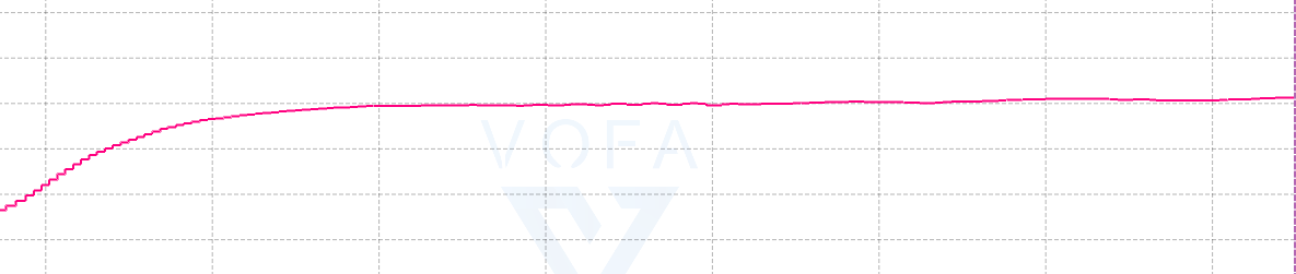
我们看一下PID控制效果:
7

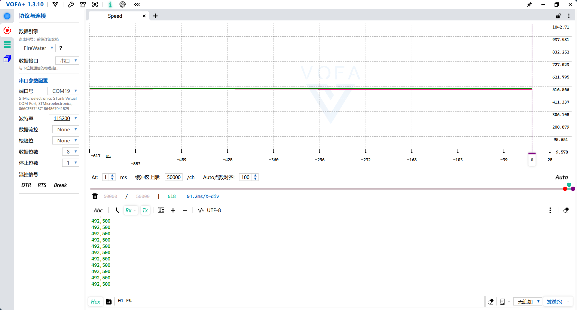
图里492是实测速度,500是输入的期望速度,可以看到效果非常不错,两条线基本贴在一起,稳态就差几个计数。这时候如果我们用力去捏电机的轴,速度只会小范围移动——负载压上来速度掉一点,误差随之变大,P项马上加大输出把速度顶回去,手一松又回到目标值,这就是闭环和开环的区别。开环的时候这么一捏速度就直接掉下去了,能不能回来得看电压和负载的脸色。这样我们的PID就算控制好了。

总结

本次尝试了一下闭环控制,算是小试牛刀(用时比深度测距用得久)。从编码器测速、FFT找频率,到双二阶滤波器和变速积分PID,整个速度环算是完整跑通了,捏住电机轴速度也能稳得住。假期会做一个六足机器人,同样会教大家一些好玩的知识,敬请期待哦!


成为控制大师[1]——闭环控制与滤波器设计
https://blog.minloha.cn/posts/1130227c2174242024063019.html
作者
Minloha
发布于
2024年6月30日
更新于
2024年6月30日
许可协议